Hydraulic clutch slave
The one part of the oval project that has given me the the most challenges is the 915 gearbox conversion. Most people that opt to go down the Porsche 5 speed route use the much easier to fit 901 gearbox from the Porsche 914 / 912. Whilst not as strong as the later 915 box it shares the VW mountings, uses a cable pull style clutch and is much simpler to install. I opted to go with the 915 as the 901 was not suitable for the power of the big Type 4 that I had planned to hook up to it, plus I did not like the dogleg shift pattern of the 901.
One unsolved issue that I have been putting off for as long as I have had the box is the clutch release mechanism. On the Type 4 engine I had a custom 911 flywheel made up, this used the 911 clutch and release bearing. The 911 clutch is a pull style clutch which means that the release arm works in reverse to a normal clutch setup. This works fine with the VW cable release although you need to figure out how to hook the cable up to the release arm, not a massive issue.
With the current power plant and the proposed 36er the clutch I am using is a traditional push style clutch which does not lend itself to the pull style operation of the 911 box. To overcome this I decided to fit a hydraulic release bearing. This is basically a release bearing that has a hydraulic cylinder integrated into it.
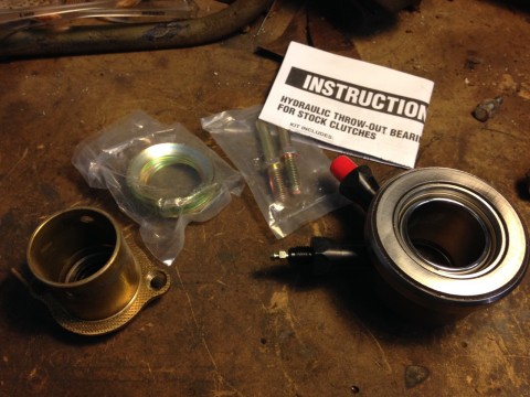
The idea is that the entire unit slips over the bearing support tube replacing the standard bearing. Well that's what happens in your average US LS1 powered car which is what this unit was originally designed for. The tube on the left of this photo is the bearing tube from the 915 gearbox. Unfortunately this is a little too large for the bearing to fit over.
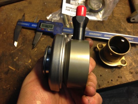
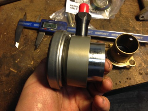
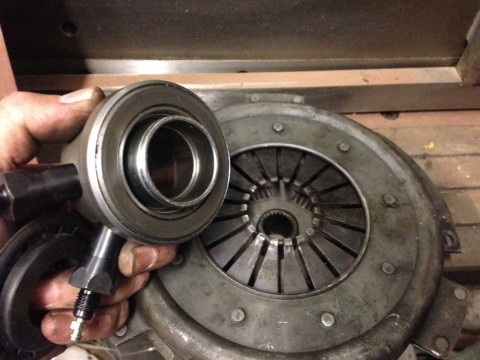
Before I go any further, and by way of an explanation the two photos above show the cylinder retracted (top) and extended (bottom). The cylinder has about 1 inch of travel. more than enough for pretty much any clutch. It came supplied with a bunch of shims that allow you to dial in it's retracted position relative to the clutch plate, these fit over the clutch tube before the hydraulic bearing is installed to bring the bearing closer to the clutch plate.
So the first stumbling block was the fact that the bearing unit did not fit over the 915 bearing tube. This was a relatively minor issue and easy enough to fix. I turned down some tubing to the correct diameter and then cut the 915 bearing tube back to the flange.
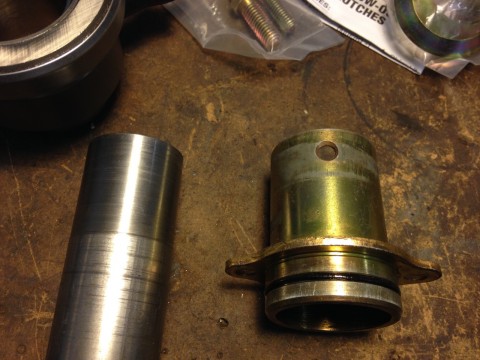
I then pressed the two parts together to make a correctly sized bearing tube.
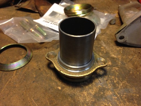
With the bearing tube finished I could not offer up the complete assembly into the gearbox.
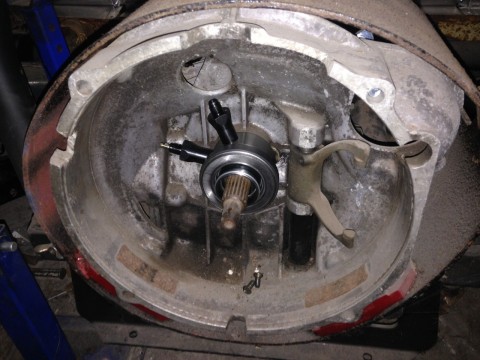
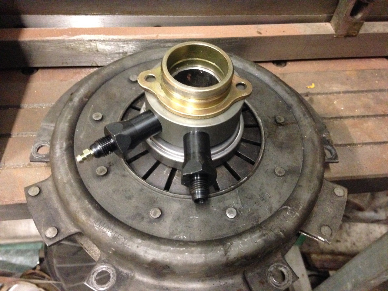
The two connections are the hydraulic connection from the foot pedal cylinder and the bleed nipple. The bleed nipple needs to be run to the outside of the bellhousing to make bleeding the clutch possible with the engine installed.
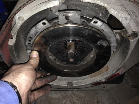
With the bearing test fitted it was time to offer up a clutch plate and try to figure out how much clearance I had and how much I needed
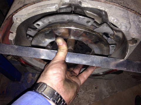
Using a straight edge things look awfully close. in fact it does not look like there is enough room for the flywheel.
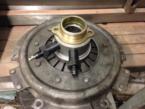
The bearing sits in the center of the flywheel but the contact points are not in line with the end of the springs on the clutch unit, this means that the clutch will rub in the center of the bearing and not on the bearing itself which is a major problem.
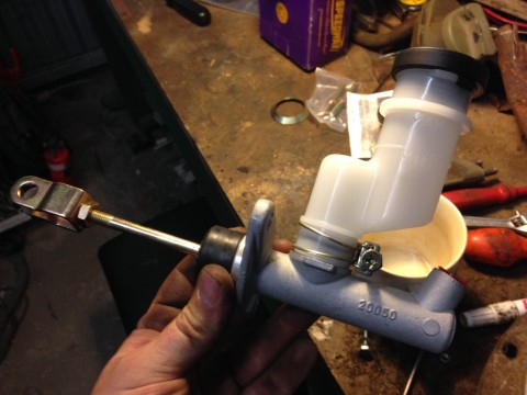
Here's a shot of the master cylinder too
At this stage it looks like I still need to gain an extra 1/2" or so. Tomorrow I will strip down the release bearing and see if there is a way that I can shorten it

Comments