Slamfest Part 2 (step-by-step)
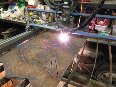
In my lasts blog post Slamfest Part 1 me and the Jimp had stripped down a bay beam and prepped a design for some new side plates ready to cut them out on my CNC plasma. Cutting out the plates was a slow affair as the cutting speed for the 10mm steel plate had to be set at about 300mm per minute, any faster and the quality of the cut suffered. The design was based on a 5 degree castor with the shock tower location moved upwards and backwards to allow for use of the stock shock.
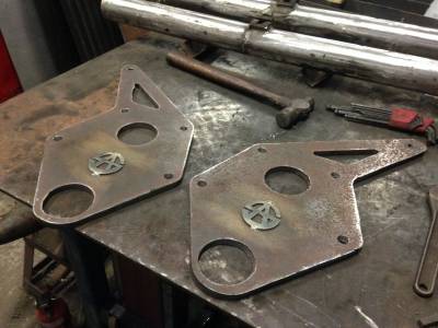
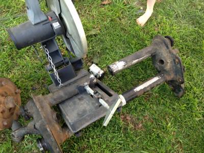
With the end plates cut out we moved on to prepping the beam. With the bay beam the best solution is to retain the outer portion of the torsion tube where the bearing is located. This allows you to also retain the roller bearings which is much better than using the urethane versions. Retaining the end part of the tubes means that all narrowing has to be done from the centre of the torsion tube. To avoid ending up with a seam in the centre of the torsion tubes the cut is offset slightly to one side of the centre. This was fairly easily achieved with some creative use of a drop saw.
With the beam cut to length the centre was knocked out of the tube and clearanced on a linisher to allow it to freely turn and then put back in the tube. The beam was then clamped up and welded back together. Although its not shown the best way to align everything is to use a couple of lengths of angle iron to clamp he two beam parts into, this ensures that it is aligned correctly. Once you have welded the two parts together you can move on to removing the old end plates.
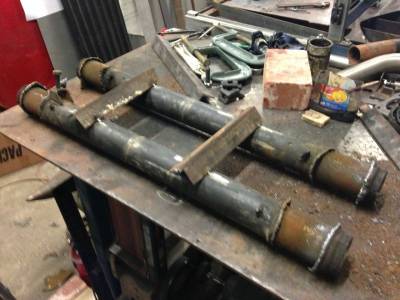
First off you will need to brace the beam so that the two tubes stay in the correct relationship to each other, this is easily done by tacking a couple of bits of scrap angle or RHS between the two torsion tubes. Once done you can then cut away the end plates. This is a bit time consuming and much much easier if you have a plasma (if you don't I'd recommend borrowing or hiring one). The more material you can remove at this stage, the better. Next stage is to grind down the remaining remnants of the side plates to leave you a a nice smooth torsion tube
With the torsion tubes cleaned up you can tackle the adjusters. The position of the adjusters will really depend on how low you plan to go, a good starting point is to use the old hole position as a reference (this means scribing the position of the hole before you do any cutting).
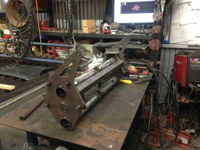
After you have the adjusters welded in its time to get everything bolted up in the jig. The Jig we used was made up from an old beam, however it would be better to make the jig from the bus as beam widths vary a little. If you make a jig like this make sure to pack out your end plates a little in the jig otherwise the beam will be very hard to fit. An even better solution is to use your bus as the jig, this way you are guaranteed for it to fit.
Check and double check everything is square and not twisted and start to tack everything in position. Don't be tempted to fully weld at this stage as the welds will pull and the beam will not be square. Once you have everything tacked together you can fully weld everything. It's important that the bearings have been removed when welding the side plates on as there is a lot of heat in this area when welding the side plates on. Once done you can remove the beam fro the jig.
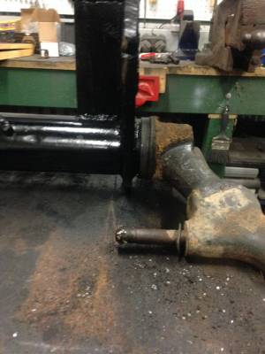
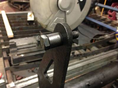
What you do next will depend on how much you have narrowed the beam. We went for 4" which which means that you will have issues with shock clearance. Not only will the shock hit the beam mounting bolts but the lower shock mounting stud will also foul the chassis. I think that this is not an issue if you go for 3 1.2" but not having built a 3 1/2" beam I cannot confirm this.
The solution is to modify the lower arm. This involves cutting the old shock mount off, drilling out the remainder of the stud and welding in a new stud. It is possible to pull the old stud out - it is secured in place by a taped pin but I found that on the arms I tried to do this it was nearly impossible and so restored to simply drilling them out - not an easy job to do as the stud is high tensile steel but possible with some patience a drill press and a decent drill bit. Once done sand the sharp edges and give everything a lick of paint and it should look like its always been this way.

The top shock mount is much easier and just requires a spacer welded on to the side plate. The hole in the beam is tapped to accept the top shock mounting bolt. (M12 from memory)
With the shocks sorted all that its left to do is weld on the pivot arm and damper mounting. I opted to move my damper above the steering arm instead of the stock location below, this works if you do not have the beam adjust too low but if you are into major slammage you might find that you have clearance issues with the gear selector shaft.

Once it's all done give it a coat of paint and start the reassembly process. Things to note are to make sure that the bearing locations don't have any burn through as this will make it harder to refit the bearings - if there is all you need to do is dress the high spots back with a die grinder or dremel. The torsion leaves will need to be cut down by 2" per side and the dimples drilled in. This is a bit fiddly to do as the torsion leaves are spring steel and you have to drill them on the edge. Best thing that I found to do was to clamp them together using a hose clamp and drill them using a drill press.
Getting the torsion leaves back in is also a major PITA, it helps to grind a chamfer on the ends to assist with getting it trough the centre adjuster. It also helps to bind the leaves together using tape - don't worry about the tape it will slide along the torsion bar when you drive it home. This really is a two person job, it's possible on your own but a lot harder.
As well as shortening the torsion leaves you will also need to shorten the track rod arms. Best way to do this is to cut 2" from one end and re-tap using an M14 tap. Make sure you get the end with the right handed thread. If you don't have an M14 tap you can also cut 2" from the middle and then re-weld them back together using round bar in the centre to add strength. Either way is fine - really depends on what tools and materials you have at hand.
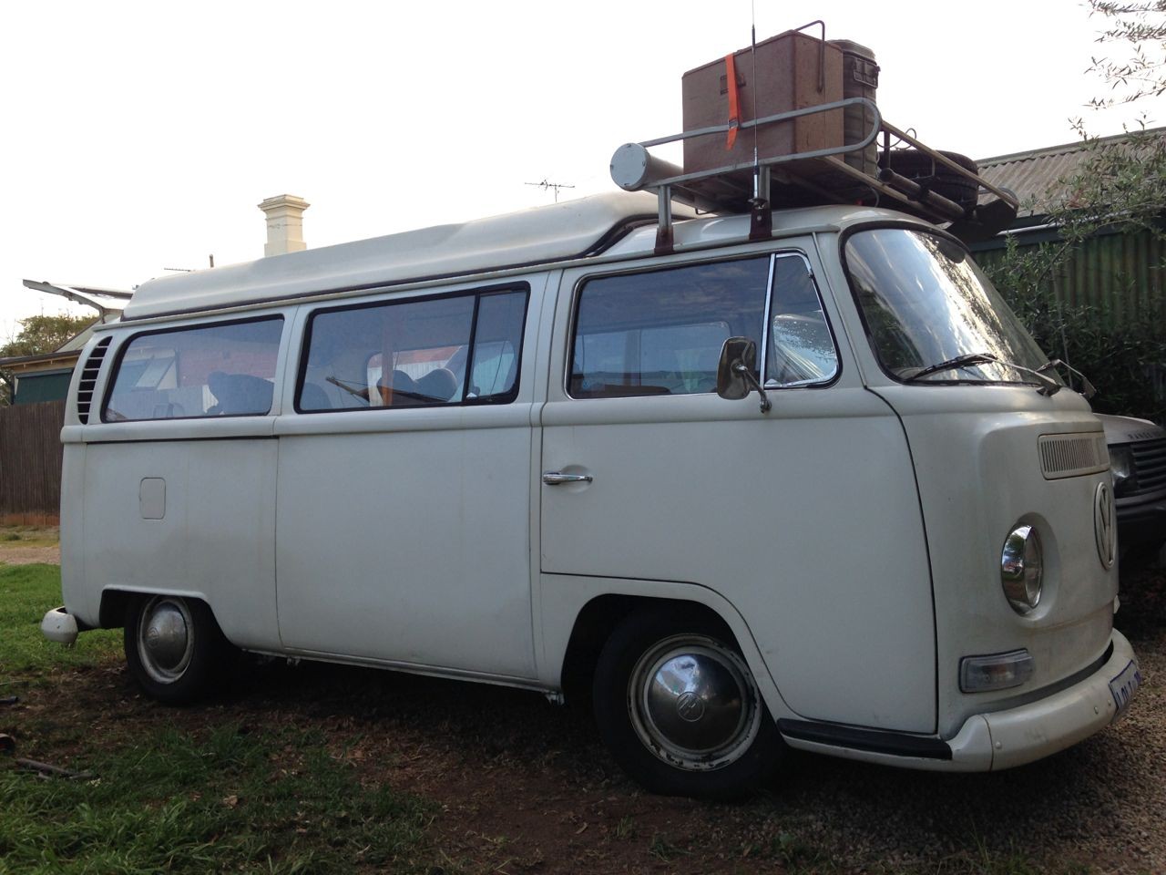
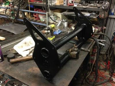
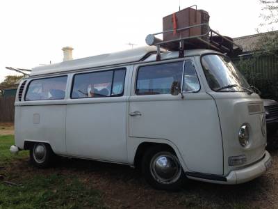
Here's the finished article - next to a stock beam and below is the beam installed in the bus. Lots of work but well satisfying
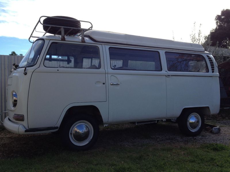
And for comparison...




Comments