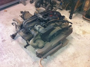
It’s been a while since I stripped a Type 3 engine, and have never worked on a fuel injected unit. There are some subtle differences between the normally aspirated unit and the fuel injected engines, the tinware is slightly different, there’s some kind of smog control valve instead of the mechanical fuel pump, The air filter is both different and in a different place and of course there is some weird looking stuff where the carburetor normally lives. The rest of the engine is basically the same.
Stripping the engine down is a fairly straight forward job and can be done in a relatively short amount of time with little more than a few spanners and sockets. I stripped off all ancillaries, tin wear and the cooling system to leave the long block with the mounting bar in place. I also stripped the starter motor and drive shafts off of the gearbox.
In short you strip off the induction system, generator, fan housing, fan, exhaust, cooling tin and heat exchangers and you’re pretty much there. (the faster you say it – the easier it sounds).
Fitting the engine in the car is pretty straight forward, I jacked the whole unit up into position, and then slid the front gearbox mount into position. I then jacked the rear of the engine up to where I thought it should be. As there was no easy way to align the position, I decided to refit the fan shroud and tin so that I could judge the alignment by looking at how the cooling tin lined up with the aperture in the body. Normally there is a rubber boot that joins the two together, and the two openings should more or less line up.
With some adjustments made to the position, a couple of things were obviously clear, Something did not quite line up right and there did not appear to be enough space to fit an IRS mounting bracket in. I was a bit perplexed and decided that there must be a difference between Type 3 and Type 34 engines – specifically the engine mounting bar. This really puzzled me as I was sure that the Type 3 and Type 34 engines were the same
So I took some photos and then compared them to the Photos that Daniel Baum kindly took of his 1969 Automatic when he had the engine out. What I initially thought must be a difference between the engine bar actually turned out to be a difference in the engine bay metalwork. IRS cars have a slightly different engine bay design. The vertical steel work to the sides finishes nearer to the front, creating a larger space to the rear – specifically to be able to easily access the IRS mounting points.
What this means in practice, is that I have limited space in which to add the mounting brackets and whilst I could modify the engine bay to suit, it would be too much work. I could also bend the engine bar rearwards a little, as this would gain some extra space.
I decided to leave the engine mounts until I can get a full clear day to concentrate on resolving the issues and make up the mountings, plus give myself a little time to ponder the best solution.
With the engine stripped and trial fitted, I decided to take the opportunity to check out some other things. One of the things I need to determine is the induction and exhaust systems. The engine will initially be installed with carburetors, for which I have a pair of 40mm Weber IDF’s. The only issue with these is that the manifolds and linkage that I have are for a bug or bus, and sit too high for use in a Type 3, unless I want to run without a engine cover.
I decided to trial fit the carbs to determine if it was easy to shorten the manifolds and get short air filters instead of replacing the whole kit. What I found was that the standard weber linkage itself is too high. With the short filters the pivot of the linkage would sit higher than the filter itself. The manifolds are also way too high and whilst it is possible to cut and re-weld them (once apon a time this was the only option) the shape of the manifold does not lend itself well to this and would require a heap of work to get them to flow nicely.
CB performance make an off the shelf IDF kit, which includes short manifolds, short air cleaners and a linkage, and for $150 it’s very reasonably priced too. The only issue is shipping to Australia, which increases the price quite a bit, but is still a better option than modifying the kit that I already have.
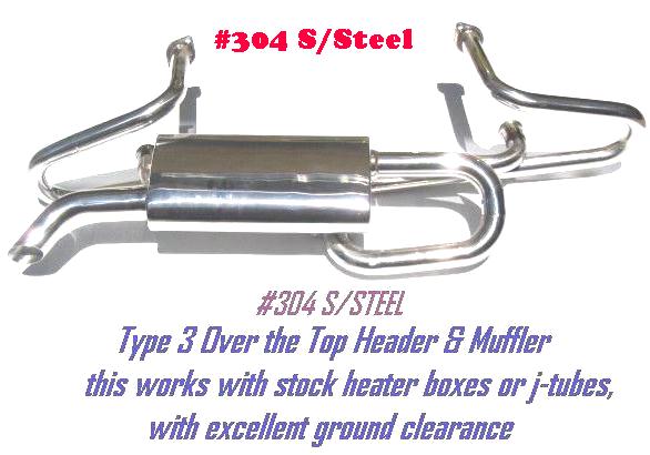
The other thing that I wanted to check out was the clearance for the exhaust system. Ive been looking at an ‘over the top’ system, this uses a merged header system that exists in a common collector much like a bug exhaust. (The headers are actually different to clear the cooling system). The silencer then sits horizontally between the collector and the fan bellows behind the valence – ie it goes ‘over the top’. The exhaust then exits in the standard location.
The system I’ve been looking at is the ISP system (shown above) which at $150 for a painted steel system is very very reasonably priced. But with over $500 postage, makes it a bit too unreasonably priced by the time it gets to Australia. There is a similar system available locally in stainless steel. But I know that a buddy of mine had fit issues when trying to fit one to his Type 34 as he found that the silencer fouled the valence.

I decide to trial fit the vintage speed exhaust that I’ve bought for the bus, and see if that would fit. Unfortunately the silencer would not fit up as it interfered with the fan housing, and the J-Tubes fouled the engine bar and the dipstick tube. But… It could actually be made to fit with a little modification and is actually quite a nice bit of kit. I might contact the manufacturer and see if they would be interested in making a system for a Type 34. This would involve different J tubes and possibly a modification to the tail pipe so that it exited in the correct place. The nice thing about this system is that it is similar in layout to the standard system and would sit behind the valence like a stock muffler.
Ultimately I decided the path of least resistance is to buy the same ‘over the top’ system that my buddy had issues with it and cut & re-weld the silencer so that it fits. Whilst I would prefer to be able to buy something off of the shelf that did not require messing about with, it does not look that that is an option. I did consider scratch building a system, but decided that I simply do not have the time.
 I also took the time to trial fit the petronix flame thrower dizzy that I have. I initially thought that this was too big to fit in next to the generator, but actually found that it fits with just millimetres to spare. The challenge will come when I try to fit an alternator. I intend to fit a beetle alternator – a conversion that whilst possible, will likely encroach on the available space and make fitting the flamethrower impossible. However, until I get the alternator, I will not know 100% for sure if this is the case. If the Alternator proves to be an issue I might postpone fitting it until I change the engine to EFI, at which point the dizzy will go in favor of a distributor-less system.


Comments 4
should be on the road by the end of the week the way you are going
should be on the road by the end of the week the way you are going ;)
Mnnn would be nice, but atill a loooong way to go.
Just ordered my engine case and some other goodies. Gotta love online shopping
Mnnn would be nice, but atill a loooong way to go.
Just ordered my engine case and some other goodies. Gotta love online shopping :D
its great if you got money to spend
its great if you got money to spend :p
LOL seems that way - but it's taken me over 15 years to get to this point.
LOL seems that way - but it's taken me over 15 years to get to this point. :D