Narrowing IRS - Part 2

If you've been following the build of the Ghia you may recall that I previously blogged about narrowing the IRS arms to help fix a tyre clearance issue that I have with the Ghia. Well having sourced another set of IRS A-arms some time back, this weekend I finally set about getting started.
My idea for narrowing the IRS arms is slightly different from the other 'how-to' threads. Instead of simply grinding the hubs out of the arms I decided to carefully grind away the weld and remove the hubs from the A-arms without taking away any additional material. To give you some idea of the 'normal' way of doing things, take a look at this thread on the Airkewld site (originally form germanlook.com but NLA). As you can see the hubs are cut out of the arms and then re-welded back in using a jig. If you cannot be bothered to read the thread, the following images will show you the basic nuts and bolts of it...


One thing to be noted, is that this is an 'extreme' narrowing job. In fact from the photo's I would say that this is a good 30-35mm possibly even 40. On the Ghia I just need to scrape 10mm to pass the engineering inspection so I'm aiming for 15mm.
As I do not need to be so extreme with my narrowing I've determined that if I can remove the hubs without damaging either them of the arm I can turn them down the the lathe to remove some material from the shoulder and then simply weld them back on. The benefit of dong it this way is that unlike the method above I can retain all of the original material of the A-arm and avoid weakening the rear hubs. You will probably note the additional strengtheners on the about arms, using my method these will not be necessary and the arm will basically retain a stock appearance - a good thing when you are about to enter your car into a full engineering inspection.
To do the job I used a thin cut off wheel in a 3.5" grinder, a dremel with a reinforced cut-off wheel and a hammer and cold chisel.
I started off by grinding through the welded portion of the outer face of the hub. This involves making a cut level with the surface of the A-arm through until you are basically the same depth as the hole visible from the inside. You will need to do this for all four 'sides'. The cut needs to extend all the way around at the same depth.
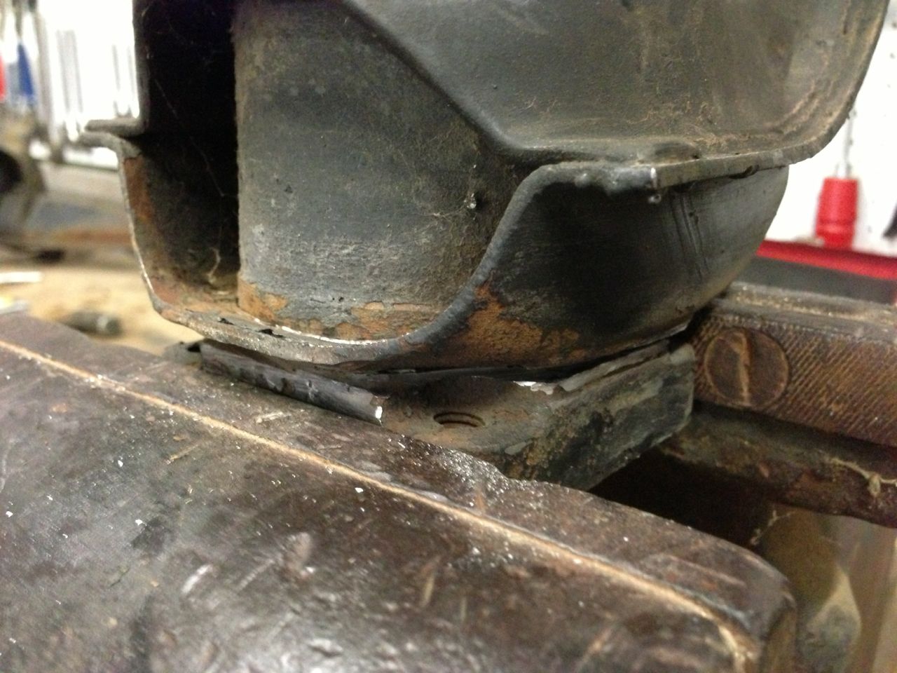
Next I ground the weld away at the read of the hub. Initially I started off with the larger grinder but I eventually swapped out the the dremel and cold chisel. The larger grinder is a little awkward to get into position all the way around the hub so you end up having to use it 'end-on'. Using it in this manner it is easy to cut a little too deep so using the dremel is a better bet here. Using the cold chisel, you can easily see if the metal is cut enough as when you hit it you will see stress cracks appearing where the metal is thinner.
The whole process is very time consuming. It's easy to simply dive straight in and grind away, but the risk with this is that you will unnecessarily damage the arm so patience is the key. I found that after a while the hub looked like it was moving a little when prying it with a pry bar but was not easy to pry out of position. I then used some long bolts and wound them into the hub mounting holes. I continued to wind them in until they bottomed out, them I wound them in some more. The bolts prized the hub out of position with relatively little effort. I had one area on the rear of the hub that needed a little more grinding to get it free, but this was easy enough to remedy.
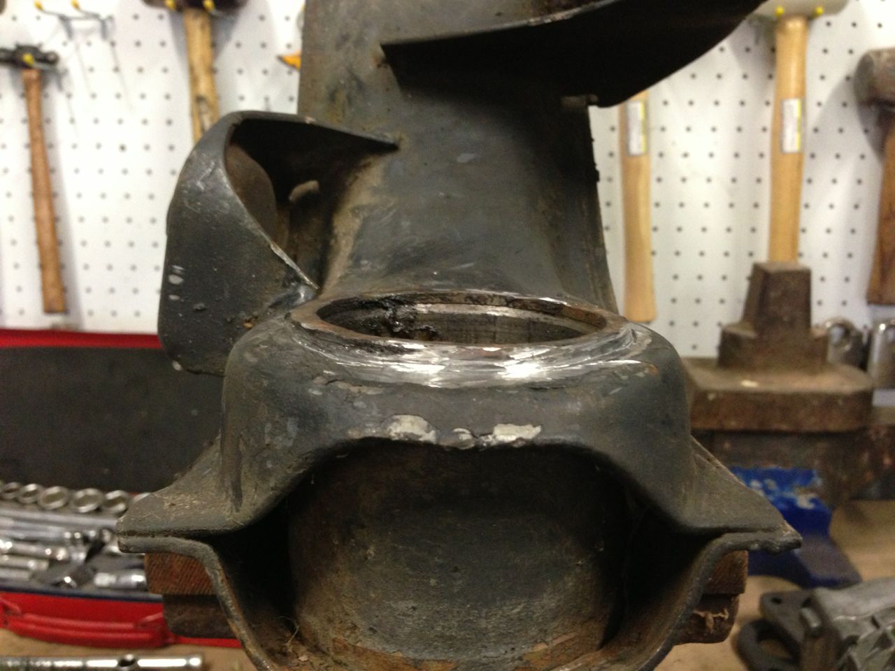
With the hub out of the arm you can see that the arm actually has two different sized mounting holes. The hole on the outside is slightly larger than the hole on the inside. These holes align with machined collars on the hub. To achieve my goal I will need to extend these collars further towards the outside of the hub. There is plenty of material on the hub to be able to happily machine the shoulder another 15mm, more than this would reduce the size of the shoulder too much and weaken the mounting points for the rear brakes. Next week I will get the hubs on the lathe and turn them down.
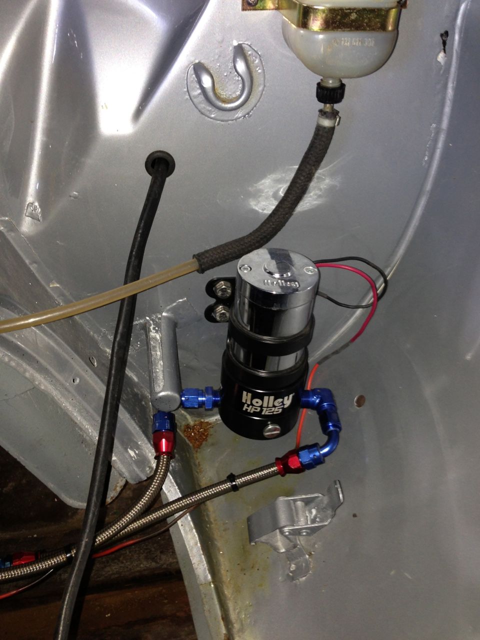
With the VEC show next weekend I also decided to fix a couple of issues such as the annoying fuel leak. I had run the fuel system in Auroquip hosing but had a minor leak in one of the fittings. Having already remade the hose off at least twice I decided to replace the flexible braided hoses with solid lines.
After testing that there were no leaks I fired her up and ran the engine for a while. Hmnnn think some valve adjustment is needed, another job for the week, maybe. Might also give her an oil and filter change as well, at the moment it is still on the running in oil as it's only done about 350k's. Was planning to run it for 500k's but at this rate, unless I get her registered it will take another year or two to clock up that many k's.
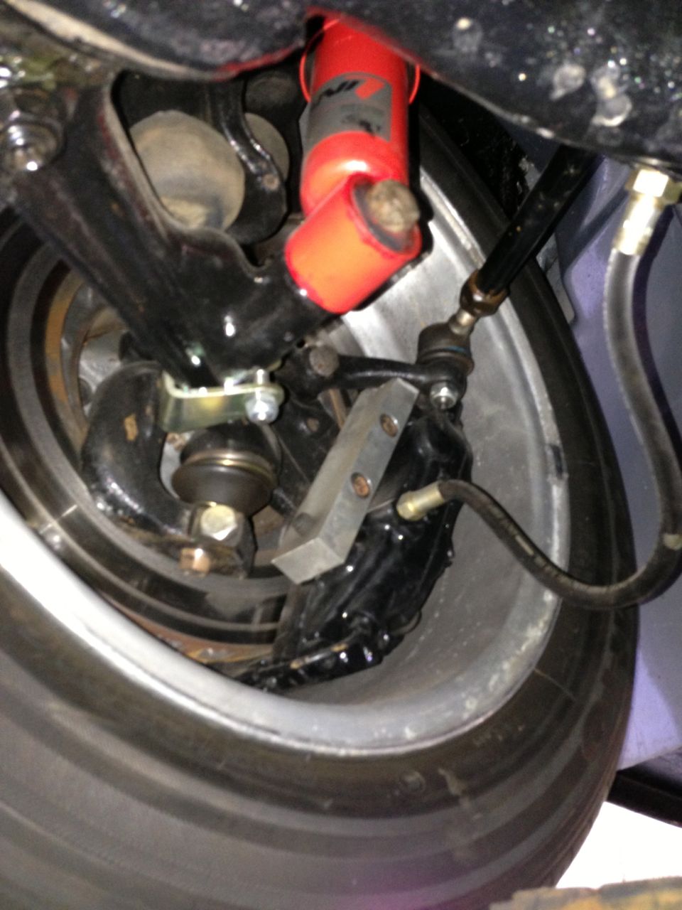
Another issue that I addressed was the clearance on the calliper The offside disc had experienced a bit of a clearance issue with the pad carrier on very hard cornering so I removed the calliper and discovered that the pad carrier had fouled the disc. This was an easy fix - I simply clearanced the carrier by grinding the end back by a couple of millimetres. I recon this must have got a bit bent when I tried to remove the carrier to paint the callipers unfortunately it would not budge so ended up staying on and getting painted along with the rest of the calliper.
Comments